

PMVSD®
The Permanent Magnet Motor and the special Variable Speed Drive (PMVSD®) are the core components of the MPS PM system. To attain the maximum efficiency while operating a PMM, the surface control logic in the PMVSD® will always be tracking the actual position of the rotor in the downhole motor to ensure that the stator magnetic field controlled by the PMVSD® is at 90° with respect to the rotor magnetic flux generated by the permanent magnets. MPS is applying a proprietary control technique to always maximize motor efficiency and generated torque at various operating conditions.
Salient Features
High performance permanent magnet motor sensor-less vector control technology
Integrated controlled sine filter for reliability in long cable applications
Integrated acquisition of drive/motor/pump operation, downhole gauge and surface process data
- Virtually unlimited internal data logging
- Retrievable memory card and wireless data transfer
- Remote control and monitoring options
Oilfield-specific process control applications like intake pressure, dewatering and low-influx.
Comprehensive alarm and automatic restart options
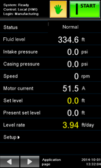
Easy to use full colour touchscreen with large clear display of 10 parameters at a time, easy navigation, touch-to-change units, security levels, graphical displays and comprehensive history reporting
NEMA 3R / 4 enclosures for worldwide use
IO terminals and air filter element accessible during operation
Latest generation power electronics and gate array computing technology
Motor Control
Sensor-less control of new-technology permanent magnet motors
For PMPCP® direct-drive motors
- Backspin control
- Low speed, < 100rpm
Scalar control of induction motors
Universal drive
Brings advanced features to conventional ESPs
Conventional ESP drives output a variable voltage at constant volts/Hz ratio and the motor controls itself as if operating off a variable utility supply. This scalar control is very simple and sufficient for induction motors used in these applications. It is possible nevertheless to over-amp the motor at start-up, just as it is when using switchboards.
MPS permanent magnet motor technology requires closed-loop control, the result of many years of application-specific research and development. These motors are synchronous, that is the applied voltage and current must be in a stable phase relationship with the rotor position. In common industrial applications like robotics, shaft sensors are used to assist the drive. With submersible motors these sensors are not feasible.
MPS drives use sensor-less control: the drive output voltage and current are measured thousands of times per second and at each point an accurate electrical model of the motor and installation back to the drive is used to adjust the output so as to maintain the rotor in synchronism. The result is stable operation with fluctuating loads, control of torque throughout the speed range – there is no danger of a snapped shaft – and in PMPCP® applications a remarkable ability to operate below 100rpm.
Operation
MPS drives are easy to set-up and operate
Select the installation type PMESP®, PMPCP® or IM-ESP
Select the application type Speed, Pressure, Level, Optimised Intermittent Lift (OiL®) or Dewatering. Anything not relevant to these one-time selections disappears.
Enter the pre-start parameters from readily available nameplate or catalogue information; check the pre-calculated alarm settings and gauge readings
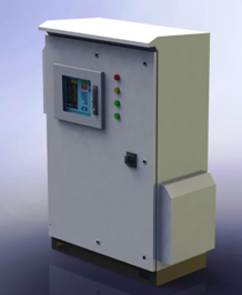
HMI
The large screen displays everything needed for routine monitoring. Touch to change the main page to list power details, gauge details and so on. Touch the Home key and a smaller display pops up for you to quickly navigate for further information.
Touch-key navigation and no numeric codes to remember or look up brings the user interface into the modern age. Touch ft to change to metres, touch ft/day for level control and change to psi/week.
Your settings are saved automatically and can be restored at any time or reverted to the settings your serviceman prepared for you. You can take the settings away on an SD card or safe keeping and apply them to another drive.
The drive logs everything all the time, and you can pop-in an SD card in the door to fetch missing files or leave it in to stay current until you are ready to collect it. Files are unique to the drive, so just use the same card for several jobs on one collection round. Drives internally record a minimum of 12 month’s data.
When no one is at the door, the display switches to monitor mode. Log-in to make changes at your privilege level.If the drive detects something you should know about, the top left status alternates with an indication – information, warning or fault; touch and up pops a list of all issues with suggestions for further action. An event viewer allows you to browse back for any significant events, like stops, starts, faults and parameter changes.
Applications
In the drive’s process applications, production is controlled using some function of process measurements like pump intake pressure to smoothly regulate motor speed. It is possible at any time to override the regulator by touching to turn to Speed control mode and touching again to revert to regulation. Mode change is bumpless – nothing sudden will happen. For example, if you temporarily go to Speed mode and do nothing, the Speed will hold at its last regulated point. Or you can change speed and later the process regulator will smoothly restore the correct speed. This is useful to temporarily observe inflow behaviour or rapidly adjust casing fluid level.
Specifications
| Physical/Environmental | ||
|---|---|---|
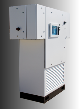
| Air-cooled Enclosure | NEMA 3R with bolt-down base | Integral junction boxes for supply and load connections. Integral data cabinet for IO connections and access during drive operation. |
| Handling | Integral plinth with fork-lift slots. Lifting eyes provided on frame size F4. | |
| Finish | White powder coating | |
| Ambient temperature – operating | -20C to +50C | Options: Cold weather and hot weather kits. |
| Altitude | 0 – 1000m | Consult for higher altitude |
| Cooling | Filter forced air. | Easy filter replacement while drive is operating. |
| Supply | ||
|---|---|---|
| Voltage | 3 phase 380 – 480VAC +5% -10% | Nominal 480VAC drives |
| Frequency | 48 – 63Hz | |
| Power factor | >95% | Fundamental |
| Protection | MOVs across lines, and to earth on grounded systems. | In incoming junction box |
| Circuit breaker | With instantaneous and thermal trip levels | |
| 50kA symmetrical breaking capacity | ||
| Soft start | Negligible inrush current, ideal for weak utility connection and generators. | |
| Harmonics and EMC | Consult factory for external low-pass filter option. Not required for generator supplies. | |
| Isolation | PMPCP® requires floating mains supply or isolating transformer. | PMESP® will normally use output step-up transformer. |
| Output | ||
|---|---|---|
| 3 phase sine wave | Integral sine filter option | |
| 358kVA nominal rating | 358kVA/0.85PF/460A/450V | |
| 132kVA nominal rating | 132kVA/0.85PF/170A/450V | |
| 100kVA nominal rating | 100kVA/0.85PF/90A/650V | For higher voltage PMPCP® applications |
| 58kVA nominal rating | 58kVA/0.85PF/75A/450V | |
| Overload | 150% for 1min/10min cycle | |
| Frequency | 60 – 150Hz (PMESP®) | |
| 1 – 30 Hz (PMPCP®) | ||
| Control | MPS Sensor-less | Permanent magnet motors |
| Speed and Process control | ||
| Scalar | Induction motors | |
| Frequency and Process control | ||
| Back-spin control unit | PMPCP® option | |
| Protection | Motor isolation switch | Required for permanent magnet motors, which generate voltage when back-spinning. |
| Comprehensive fault protection and event log diagnostic reporting | Short circuit, over-load, under-load, thermal, internal faults, supply fault – over 100. | |
| User-accessible trip loop | 24V loop bypassing electronics and firmware. | |
Output ratings are at nominal supply voltage and without sine filter option.